Contents
Approved by Kurt Ettinger
Revised 8/25
29.1 Policy
29.2 Scope and Applicability
29.3 Roles and Responsibilities
29.4 Definitions
29.5 Required Work Processes
- Work Process A. General Cryogen Information
- Work Process B. Working with Cryogens and Cryogen Systems
- Work Process C. Oxygen-Deficiency Risk Assessment
- Work Process D. Engineering Controls and System Requirements
- Work Process E. Personal Protective Equipment for Cryogen Handling
- Work Process F. Training
- Work Process G. Verification of Controls
- Work Process H. Work Procedures for Handling and Transportation
- Work Process I. First Aid for Cryogen Contact
- Work Process J. Waste Disposal
- Work Process K. Reporting Incidents: ES&H Documentation and Reporting/Notification
29.6 References
29.7 Appendices
- Appendix A. Common Cryogen Systems
- Appendix B. An Overview of the ODH Calculator Model
- Appendix C. Liquid Helium
- Appendix D. Liquid Hydrogen
- Appendix E. Liquid Oxygen
- Appendix F. Calculations for Oxygen Deficiency When Storing and Filling LN2 Dewars
Note:
🚩🚩 Denotes a new section
🚩 Denotes the beginning of changed text within a section
🛑 Denotes the end of changed text within a section
_____________________
29.1 Policy
This policy describes the safe handling requirements for persons who work with cryogens or operate cryogenic-liquid-handling systems at Lawrence Berkeley National Laboratory (LBNL). This document is not a substitute for On-the-Job Training (OJT).
29.2 Scope and Applicability
A cryogen or cryogenic liquid is defined by the National Institute for Standards and Technology (NIST) as any liquid with a boiling point below 93K (-180°C or -240°F) at 1 atmosphere of pressure. This definition includes liquid nitrogen, liquid argon, liquid helium, liquid hydrogen, and liquid oxygen, among others. This definition does not include, and this policy does not cover, liquid propane, liquid butane, liquid acetylene, or liquefied natural gas (methane).
This document addresses cryogenic safety with a primary focus on and specific examples of the inert cryogenic liquids of liquid nitrogen, liquid helium, and liquid argon. Liquid helium, liquid hydrogen and liquid oxygen present additional hazards above liquid nitrogen and liquid argon. For more information on liquid helium, liquid hydrogen and liquid oxygen, see Appendices B, C and D, respectively.
NOTE: Liquid nitrogen is the most frequently used cryogen at LBNL.
All LBNL employees, visitors, affiliates, and subcontractors who handle cryogens or operate cryogenic-liquid-handling systems at LBNL must follow these guidelines:
- Be aware of the hazards related to the equipment.
- Know the methods for controlling those hazards.
- Follow the proper operating procedures applicable to the equipment.
- Work under an approved activity in the Work Planning and Control System.
- Receive on-the-job training from the Activity Lead for that activity.
A thorough evaluation of the safety of a cryogenic application may require a joint effort involving the Environment, Health & Safety (EHS) Division (Safety Engineering and the EHS Research Support Team) and the Facilities Division (Transportation and Rigging Groups).
29.3 Roles and Responsibilities
|
Role |
Responsibility |
|
Facilities Division
|
|
|
EHS Research Support Team Subject Matter Expert (SME) |
|
|
Line Managers
|
|
|
Supervisors and Work Leads
|
|
|
Cryogenic Liquid Users |
|
In the event of an emergency, LBNL staff and affiliates must:
- Evacuate and not enter the area when oxygen monitors indicate a lack of oxygen.
- Notify personnel in surrounding areas who may be affected.
- Seek medical attention for any injuries or cryogenic burns.
- Report the event to their work lead, supervisor or the LBNL emergency number (510) 486-7911 or 911.
- For off-site locations (e.g., Potter, JBEI, JGI, etc.), use the local emergency number.
29.4 Definitions
| Term | Definition |
| Asphyxiation hazard | The risk of death due to low oxygen concentration caused by the expansion of cryogenic gas into a limited space, displacing oxygen. |
| Cryogenic burn | Localized damage to skin and tissue due to contact with cryogenic liquids or materials, or even gases cooled to cryogenic temperatures. |
| Cryogenic liquid/ cryogen | Any liquid with a boiling point below 93K (-180°C or -240°F) at 1 atm pressure. This includes, but is not limited to, liquid nitrogen, liquid helium, liquid oxygen and liquid argon. |
| Cryogenic liquid cylinder | A pressurized double-walled vessel, evacuated between the walls that allows for the pressurized storage of cryogenic liquids for weeks or months. Either liquid cryogen or the gas phase may be extracted from a cryogenic liquid cylinder. |
| Dewar, or cryogenic liquid dewar | A double-walled vessel, evacuated between the walls that provides thermal insulation to store liquid cryogens for days at a time. Dewars have loose fitting or vented caps to allow for escape of gas as the cryogenic liquid evaporates. |
| Dewar flask | A double-walled vacuum vessel with an open top. A loose fitting foam lid may be provided to reduce evaporation rate. These flasks are intended for the open use of liquid cryogen and not for storage. |
| Dry/vapor shipper | A double-walled vacuum vessel that contains an absorbent material capable of absorbing liquid cryogen and an internal space for racks of samples that is capable of maintaining cryogenic temperatures of the samples during shipping, but which does not need to contain free liquid cryogen in order to keep samples cryogenically frozen. When properly used, Dry/Vapor Shippers do not present a risk of cryogenic liquid spills. |
| Frostbite | Localized damage to skin and tissues due to exposure to freezing temperatures, often directly caused by a prolonged lack of blood flow to the area. |
| Oxygen deficiency | A localized concentration of oxygen that is well below normal oxygen concentration in air. Any local oxygen concentration below 19.5% by volume constitutes an oxygen deficiency. |
| Oxygen deficiency hazard/ODH | The extent of the risk to life or health due to a locally decreased oxygen concentration. |
| Oxygen enrichment | A localized concentration of oxygen exceeding normal oxygen concentration in the air (> 23.5% by volume), which can accelerate oxidation and combustion. |
| Thermal stress | Stress that a material undergoes when it changes temperatures. As materials are heated and cooled they expand and contract. The entire piece of the material does not expand or contract at the same rate, causing stress that may damage or break the material. |
29.5 Required Work Processes
Work Process A. General Cryogen Information
1. Identifying Hazards Associated with Inert Cryogenic Liquids
The following tables identify the properties of and major hazards associated with the use of inert cryogenic liquids, focusing primarily on liquid nitrogen. The hazard list should not be considered exhaustive.
Table A.1 Physical Properties of Selected Cryogenic Liquids
| Cryogen | Temperature @ 1atm °F/(K) | Liquid/gas expansion | Pressure generated from trapped liquid–allowed to warm to room temperature |
| LO2 | – 297 (90.2) | 860 to 1 | 12,600 psig |
| LAr | – 302 (87.3) | 847 to 1 | 12,300 psig |
| LN2 | – 320 (77.4) | 696 to 1 | 10,200 psig |
| LH2 | – 423 (20.3) | 851 to 1 | 12,400 psig |
| LHe | – 452 (4.2) | 757 to 1 | 11,000 psig |
Table A.2 Cryogenic Hazards
|
Hazard |
Description |
|
Thermal (low temperature) |
|
|
Pressurization |
|
|
Venting |
Required vents and pressure-relief devices must be vented to a safe location, which is determined with the following criteria:
|
|
Oxygen deficiency/asphyxiation |
Cryogenic fluids have large liquid-to-gas expansion ratios:
These ratios mean that any accidental release or overflow of these cryogenic liquids will quickly boil into gas and may create an asphyxiation hazard by displacing the oxygen content of the surrounding area.
|
|
Ice buildup |
|
|
Materials concerns |
The low temperature of cryogenic liquids will adversely affect the properties of some materials, resulting in system or vessel failure. The process for selecting materials to construct vessels and piping systems for cryogen handling must consider the behavior of the materials at cryogenic temperatures.
Even when the appropriate materials are selected, thermal stresses can lead to failure in some applications. Joining materials with dissimilar coefficients of expansion can also generate thermal stresses. All components selected and used in cryogenic liquid systems must be designed and manufactured for such service. |
|
Oxygen enrichment |
Liquid nitrogen is cold enough to condense the surrounding air into a liquid form. The concentration of oxygen in this condensed air is enhanced. This condensed “liquid air” can be observed dripping from the outer surfaces of uninsulated/nonvacuum-jacketed lines carrying liquid nitrogen. This “liquid air” will be composed of approximately 50% oxygen and will amplify any combustion/flammable hazards in the surrounding areas.
|
|
Lifting, physical |
Studies of accident statistics involving cryogenics commonly include back strains or other lifting injuries associated with dewars. Although not specifically cryogenic in nature, this hazard is appropriate to note as a hazard associated with cryogenic applications.
|
|
Ionizing radiation fields |
Using cryogens in high ionizing radiation fields that can generate ozone or nitrogen oxides may cause a potential explosion hazard when the cryogen condenses quantities of oxygen from the atmosphere. The applicable control measure is to minimize the accumulation of oxygen into the cryogen and to keep containers free of hydrocarbon contamination. |
|
Noise |
Transfer or venting of cryogens can generate, in some cases, noise levels that may require hearing protection. Sound levels in excess of 150 dBA have been recorded during routine tank filling. A redesign of the equipment or procedure could also be addressed in these cases. |
|
Other, specific |
Other cryogenic liquids present specific hazards in addition to the above concerns. Examples include:
This list is not to be considered exhaustive. Seek additional guidance from the appropriate division ES&H team for a thorough hazard analysis and safe operation of these systems. |
2. Potential Accidents with Cryogenic Hazards
LBNL staff and affiliates must be aware of the possible accident scenarios for the LBNL environment. The following table lists known, common accident scenarios involving cryogen applications.
Table A-3: Potential Accidents
|
Potential Accident |
Description |
|
Accidental releases (or overflows) |
Accidental releases (or overflows) of cryogenic liquid can present hazards and cause property damage, as noted in the hazards discussed above.
|
|
Releases into building exhaust systems |
Releases into building exhaust systems also can present significant hazards.
|
|
Pressure buildup (pressure relief valves, PRVs) |
Pressure relief valves (PRVs) are required on cryogenic-liquid piping systems to prevent excess pressure buildup when the liquid is trapped between closed valves.
|
|
Back injuries |
Back injuries may result from lifting cryogenic-liquid dewars. |
|
Tipping of dewars |
Storage dewars may be accidentally tipped over when crossing obstructions, such as door thresholds.
|
|
Accidents caused by equipment failure (equipment not designed for cryogenic service)
|
Cryogenic liquids should only be handled in apparatuses specifically designed for that purpose.
|
|
Slips, trips, and falls |
Cryogenic liquid containers may condense and/or freeze water from the air and leave water on the floor where workers may slip.
|
Table A.4 The Effects of Oxygen Deficiency
% Oxygen by Volume at Sea Level | Effects of Acute Exposure |
| > 19.5 | None, atmosphere is not oxygen deficient. |
| 17 – 19.5 | Mild effects similar to exposure to increased altitude. |
| 16 – 17 | Reduced night vision, increased breathing volume, accelerated heartbeat, fatigue upon exertion. |
| 15 – 16 | Dizziness, increased reaction time, fatigue upon mild exertion. |
| 12 – 15 | Impaired attention, impaired judgement, impaired coordination, intermittent breathing, rapid fatigue, loss of muscle control. |
| 10 – 12 | Very faulty judgement, very poor muscular coordination, loss of consciousness, permanent heart or brain damage possible. |
| 6 – 10 | Inability to move, nausea, vomiting. |
| 6 or less | Spasmodic breathing, convulsive movements, death in 5-8 minutes. |
Further Information
Many of the hazards associated with cryogen use are not unique to cryogens. The following table lists some common hazards and where to find more information:
| Hazard/Activity | Reference |
| Confined spaces | Chapter 34 Confined Spaces |
| Pressure | Chapter 7 Pressure Safety |
| Skin burns | Chapter 4 Exposure Assessment Section 4.7 |
Work Process B. Working with Cryogens and Cryogen Systems
Before beginning any work with cryogens or cryogen systems, workers must be familiar with the cryogenic equipment and systems they will be using.
Using the Work Planning and Control Activity Manager system, in the Description of Work, activity leads shall identify the cryogen equipment and systems to be used, e.g., low pressure storage dewars, open dewar flasks, cryogen cooled vacuum traps, dry/vapor shippers, cryogen filling stations, etc. The Description of Work may also contain procedural information regarding the use of such equipment. The Activity Lead shall read all manufacturer’s instructions regarding the use of and controls for commercially obtained cryogen equipment, and make available this information to all workers on the Activity. For some cryogen systems, On-the-Job Training (OJT) may be required. It is highly recommended that this OJT requirement be documented in the Controls of the Activity.
Appendix A contains detailed information on some of the most common cryogen systems.
Note: When setting up, installing or designing any cryogen system, appropriate materials must be selected, and appropriate controls must be followed as for pressure systems, outlined in ES&H Manual Chapter 7, Pressure Safety.


Table B.1 Responsibilities for working safely with cryogens and cryogen systems
|
Project Lead/PI |
|
|
Activity Lead |
|
|
Worker |
|
Work Process C. Oxygen-Deficiency Risk Assessment
An easy-to-use oxygen-deficiency hazard (ODH) calculator has been developed as a screening tool, and can be used in many cases. However, sometimes the complexity of a cryogenic system will require a more in-depth quantitative analysis.
1. Requirements
Before work with cryogenic liquids is undertaken, an oxygen-deficiency risk assessment must be conducted. There are two types of risk assessments that may be done:
- Qualitative – easy to use but limited to simple cases
- Quantitative – will require the use of a detailed and complicated model and to work with the Cryogenic SME
The ODH assessments will need to address the risk of asphyxiation as well as risks from contact with the cryogenic liquid. Any reasonably foreseeable accidents (i.e., spillage, ice plug, cold burns, etc.) should be taken into account and appropriate contingency plans implemented to deal with such emergencies.
| Assessment Results |
| Results of the risk assessment will be used to define cryogen controls. See Appendix B for additional details on the risk-assessment process for oxygen-deficiency hazards. |
| Results of qualitative and quantitative risk assessments will be stored in the CHESS database for future reference and for use in establishing Work Planning and Control activities as required. |
| For Risk Assessments that result in an Oxygen Deficiency Hazard Class of 1 or above, additional EHS review will be required. Based on the professional judgment of the Cryogenic Subject Matter Expert (SME), activity may be increased to Risk Level 3 and may include control measures as detailed in Table C-2. |
2. Qualitative Oxygen-Deficiency Risk-Assessment
The oxygen-deficiency risk assessment will take into account the location of work and room size. Small or poorly ventilated rooms have a much higher risk of asphyxiation due to oxygen deficiency.
For qualitative assessments of the potential to create an oxygen-deficient atmosphere, the simple ODH calculator will be used. To download the ODH Calculator, go here. For more information about the ODH calculator, see Appendix B. An example of the actual output from the analysis of a laboratory is shown below.
ODH Calculator
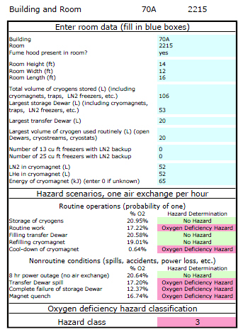
If oxygen levels could fall below 19.5% during routine operations, suitable control measures should be implemented, e.g., filling or storing vessels in a ventilated room, installing a permanent oxygen monitor, or using smaller storage vessels. An example of a better-ventilated room will generally include a lab with an active fume hood with at least 25% bypass airflow and an active flow-monitor alarm that is set up so the alarm cannot be disabled by local residents.
Situations in which the ODH Calculator is not suitable for ODH determination:
- Handling or storing cryogenic liquids in a container not specifically manufactured for cryogen service.
- Employee-built cryogen storage/handling apparatus.
- Plumbed cryogen systems – any situation in which cryogenic liquid is run through plumbing external to the storage cylinder.
- Use of cryostats or cryogen baths used for cooling
- Exception: the cryogen cooling system built into a commercially available cryomagnet such as an NMR system.
- Filling of cryogen storage cylinders or dewars indoors.
In these situations a quantitative assessment must be performed.
| Understanding Oxygen-Deficiency Calculator Results and Limitations |
| If there is no oxygen deficiency hazard for any routine condition and the ODH hazard class is zero, no further action is required. |
| If either the ODH hazard is not zero or an oxygen deficiency hazard is possible for any routine operation, the ODH of the room must be analyzed by an industrial hygienist, and further engineering and/or administrative controls may be required. |
| The ODH calculator is not for use with plumbed liquid nitrogen supplies; the ODH of these locations must be evaluated by other methods. (Contact the Cryogens SME for more information) |
| If the room has activities that do not map onto the scenarios in the ODH calculator, the ODH must be determined by other methods. (Contact the Cryogens SME for more information) |
3. Quantitative Oxygen-Deficiency Risk-Assessment
Examples of acceptable quantitative methods for oxygen-deficiency risk assessment methodology include, but are not limited to, the Fermi Lab ODH methodology. While this is a complex and lengthy approach, it has the advantage of being applicable to any cryogenic liquid system and application, including custom-built systems. If a system cannot be modeled with the qualitative ODH Calculator (section 2 above), contact the Cryogenic Liquids SME for a full quantitative risk-assessment.
The quantitative risk-assessment model will result in a fatality rate per hour for the overall use of the proposed cryogen system. Once the fatality rate (f) has been determined, the operation will be assigned an ODH class according to Table C.1 below, where the Risk [f] (hr-1) represents the probability of a fatality occurring per hour in the room. This model takes into account various failure rates and human error rates for the equipment and plumbing involved, and assumes that no oxygen monitors or other safety measures are in place. A risk of 10-7 represents a 1 in 10,000,000 chance of a fatality per hour, and a risk of 1 would theoretically indicate that anyone who enters the room would certainly die within an hour.
Table C.3 Oxygen-Deficiency Hazard (ODH) Classes
| Oxygen-Deficiency Hazard (ODH) Class | Risk [f] (hr-1) |
| 0 | <10-7 |
| 1 | > 10-7 but <10-5 |
| 2 | > 10-5 but <10-3 |
| 3 | >10-3 |
The quantitative risk assessment must be conducted by the Cryogenic Liquids SME.
Once the ODH hazard class has been determined, workplace controls can be put in place to minimize the risks. See Work Process D.
4. General Guidelines for Cryogen Use
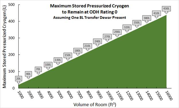
The following chart is intended to give a rough approximation of the limits for cryogen use based on the room size and volume of cryogen stored. This information is not to be used in place of an Oxygen Deficiency Hazard analysis as discussed in sections 1 through 3 above, but is merely intended to allow the reader to get a sense for what is and is not possible for a given space.
Chart C.1 Maximum Pressurized Cryogen Storage with ODH Rating 0
Chart C.1 assumes that the cryogen user will store one pressurized cryogen cylinder in the room, for the purpose of supplying inert gas to some piece of equipment or instrumentation. The calculation allows for the simultaneous storage of one 8L non-pressurized transfer dewar, but does not allow for filling of the transfer dewar from the storage dewar. Filling of a transfer dewar in an enclosed space adds significantly to the oxygen deficiency hazard.
Work Process D. Engineering Controls and System Requirements
1. Pressure Relief Valve (PRV) Requirements
Pressure relief valves, or PRVs, used on cryogenic liquid systems must be compatible with cryogenic temperatures and with the physical and chemical properties of the cryogen they are intended to vent. Most importantly, pressure relief valves must not cease to function in extreme cold temperatures 

As described in Work Process A, cryogenic liquids can build up extreme pressures if confined and allowed to warm. Cryogenic systems must be designed such that every isolatable part of the system which could conceivably have cryogenic liquid or gas introduced must have its own pressure relief, in the form of a valve or burst disk with adequate gas flow capacity, to prevent explosion from trapped cryogen.
2. Manual Shutoff Valves
All cryogenic liquid systems which supply cryogenic liquid or vaporized gas from a cryogenic liquid source shall have a manual shutoff valve which is accessible form the point of use. This manual shutoff valve shall not be located in a hazardous area. If the point of use is immediately near the main cylinder valve, then the main cylinder valve is considered to be a manual shutoff valve for this purpose as long as the valve is readily accessible by anyone operating the system.
 3. Insulation and Protection from Inadvertent Contact
Wherever practical, people must be protected from inadvertent contact with cryogens or cryogenically cooled parts of a system. This may be achieved through the use of covers, guards, and/or insulation. Where covering, guarding, or insulating the hazard is impractical, PPE must be utilized. See Work Process E.

4. Additional Controls for Handling Cryogenic Liquids
Depending on the results of the Oxygen Deficiency Hazard (ODH) risk assessment (see Work Process C), a variety of engineering controls may be required to be implemented to safely handle cryogenic liquids. Table D.1 below lists possible engineering controls based on the Oxygen Deficiency Hazard class. This list is not exhaustive.
Table D.1 Possible Oxygen Deficiency Hazard Control Measures
| Control | Hazard Class 1 | Hazard Class 2 |
| Warning signs | X | X |
| Oxygen monitor | X | X |
| Ventilation | X | X |
| Medical approval | X | |
| ODH training | X | X |
| Personal oxygen monitor | X | |
| Self-rescue respirator | X | |
| Communication system | X | X |
5. Cryogen Signs
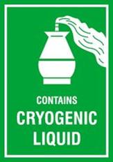
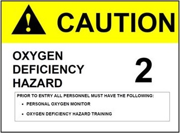
Entrances to labs that use cryogens must be posted with cautionary signs labeled with the cryogen icon (see below), as required by LBNL’s Chapter 45 Chemical Hygiene and Safety Plan.
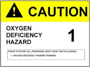
Additionally, for work areas that require significant time to evacuate (e.g., tunnels, caves, and similar areas) and where the potential for oxygen deficiency hazard level is “1” or above, the following signs must be posted at the entrance to the space:
Cryogen bulk filling stations must post a sign with a minimum of the following information:
- Personal Protective Equipment is Mandatory for use of the Filling Station
- Required PPE includes:
- Face shield over safety glasses
- Cryogen gloves
- Long cuffless trousers
- Closed toe shoes
- Long sleeves or laboratory coat
Additionally, owners of bulk filling stations are highly encouraged to post a sign indicating the responsible persons for arranging cryogen delivery to the bulk station and for training new users to safely dispense cryogen.
Work Process E. Personal Protective Equipment for Cryogen Handling
Engineered controls should be the primary means of worker protection. Where engineered controls cannot fully mitigate all hazards, workers must wear the appropriate PPE to augment any controls in place.
Certain types of operations may increase the risk of exposure to cryogenic liquids. Selection of appropriate PPE must include careful consideration of the specific system configuration and the potential for exposure to all potential hazards. Examples of this include:
- Pressurized liquid nitrogen dewar-filling operations where Berkeley Lab staff and affiliates could be exposed to pressurized sprays or splashing.
- Making or breaking of pressurized cryogen line connections where residual amounts of liquid or gas under pressure may be encountered.
- Inserting room temperature objects into cryogenic liquid baths producing rapid boiling of the cryogenic liquid.
Many other operations are considered low risk, and Table E.1 below summarizes the required PPE for low risk operations.
Table E.1 Summary of PPE Requirements for Low Risk Cryogen Operations
Operation | Potential Hazard | Face Shield and Safety Glasses (with Side Shields) | Safety Glasses (with Side Shields) | Cryogen Gloves | Closed-Toe Shoes | Long Trousers (No Cuffs) | Lab Coat or Long-Sleeve Shirt | Remarks |
| Pouring small nonpressurized (<5 liters) volume of LN2 between open containers | Eye or skin injury from splashing | X | R1 | X | X | R1 | Avoid pouring cryogens from above chest level. | |
| Work with experimental samples immersed in LN2 in small (≤1 L) dewar | Frostbite and burns from cold surface contact | X | R1 | X | X | R1 | Thermally insulated hand tools may be an effective alternative to gloves. | |
| Handling chilled metal transfer lines | Frostbite and burns from cold surface contact | X | X | X | X | X | ||
| Dispensing LN2 from a pressurized line to an open dewar2 | Frostbite and burns from cold surface contact, eye and skin injury from splashing | X | X | X | X | X | X | Example: Operating a fill station |
| Closed pressurized line LN2 or LHe transfer | Frostbite and burns from contact with the unexpected release of pressurized cryogen liquid or gas | X | X | X | X | X | X |
1 Recommended. For a few limited operations, cryogen gloves or long-sleeve shirts/lab coats may not be needed.
2 When using a phase separator between the pressurized LN2 line and the open unpressurized dewar, the risk of a cryogen splash is substantially reduced.
Selection of PPE for Work with Cryogens
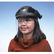
- Face Shields
The primary function of a face shield is to protect the head and face in case of a splash. A good face shield should have adjustments to fit many head sizes and should provide good coverage of the entire front of the head, including around the sides. Some mechanism to lock the shield in place so that it doesn’t slip down and touch the chest is recommended to improve comfort. The shield should have a sloped top surface to direct splashes away from the top of the head and to prevent splashes from getting behind the shield from above. Even better is a face shield with impact resistance, per ANSI Z87.1, which is indicated by a marking of “Z87+” on the face shield surface, but this is not a requirement. Some models have replaceable clear shields so that when the shield becomes scratched or dirty, it can be replaced without purchasing new headgear.
NOTE: You must still wear safety glasses underneath the face shield.
The following image shows an acceptable use of a face shield to protect against cryogen splashes:
Photo Copyright © Cole-Parmer.
- Cryogen Gloves
Cryogen gloves should be made of non-porous material and should never be confused with heat resistant gloves. Cryogen gloves used to handle hot objects will likely melt, while heat resistant gloves used for cryogens offer no protection from frostbite or burns and can actually trap cryogen against the skin in the porous material of the glove. Ideally, cryogen gloves will be loose fitting and easy to remove. This feature makes it easy to get the glove off in a hurry if cryogen ever becomes trapped inside the glove against the skin.
Before using cryogen gloves, always inspect them for ripped seams, tears or holes where cryogen could get inside the glove.
NOTE: Cryogen gloves are intended for handling very cold items and to protect against an accidental splash. They are NOT meant to be submerged in a cryogenic liquid.
The following image shows a pair of cryogen gloves:

- Long Pants/Trousers
Long pants/trousers are required during all work with cryogenic liquids; shorts and cropped pants are unacceptable. Furthermore, pants/trousers with cuffs can trap cryogenic liquid in the fold of the cuff and against the skin, increasing the chance of cryogenic burns. Cuffed pants/trousers are not permitted to be worn when handling cryogens. It is also recommended to wear loose-fitting pants/trousers so that any spilled or splashed cryogens will roll off the fabric without transferring significant heat into the skin. Tight jeans or leggings provide less protection against cryogen splashes.
- Closed Toe Shoes
It is increasingly common to wear athletic shoes into the laboratory, which are often designed to keep the feet cool, with webbed mesh tops for air flow. Unfortunately, if the shoes allow airflow, they will also allow cryogen into the shoe through the top in the case of a spill or splash, and are often time consuming to remove. Appropriate shoes for use with cryogenic liquids should cover the entire top of the foot and should be able to at least temporarily repel liquids. Shoes with webbed or mesh tops are not permitted when handling cryogens*.
*Closed toe shoes without mesh tops are required. Shoes with enclosed heel and entirely covered tops are recommended.
Work Process F. Training
LBNL staff and affiliates must complete the required training identified below before performing the indicated work activity or fulfilling the indicated role. Untrained LBNL staff and affiliates may temporarily work under the direct supervision of an appropriately qualified supervisor or work lead if the conditions/limitations of such work are documented (e.g., specific activities and duration) before performing the work.
| Requirements for LBNL Staff and Affiliates Handling Cryogenic Liquids |
| Complete EHS0170 as required by this chapter. |
| Contact the Activity Lead for the operations you wish to perform and get added to the activity in WPC. Read and understand all required work descriptions and controls. |
| Receive on-the-job training on site-specific procedures for safe operations from your Activity Lead before beginning operations involving cryogens. |
| Obtain authorization from your Activity Lead to perform work as described in the activity. |
NOTE: This document is not a substitute for on-the-job training. The Activity Lead for your cryogen-related WPC Activity is the only one who can grant you authorization for any cryogen work.
Work Process G. Verification of Controls
Depending on the outcome of the hazard assessment, the Cryogens Subject Matter Expert, or SME, may need to verify all designated controls are in place prior to the start of cryogen use. The Principal Investigator will arrange for the verification if one is indicated as part of the planning and assessment process.
Work Process H. Work Procedures for Handling and Transportation
The following sections give an overview of good laboratory practice for a variety of operations involving cryogens. However, this document is not a substitute for on-the-job training. Always get the appropriate OJT from your Activity Lead before performing any work.
- Work with Open Dewar Flasks
The main hazard associated with working with dewar flasks is burns from cryogen spills or cryogen-cooled tools. Performing any work with open dewar flasks requires the use of safety glasses with side shields, cryogen gloves†, long pants and closed toe shoes, and a lab coat or long sleeves. A lab coat is recommended as the safer option. The following are good laboratory practices for working with open containers of cryogenic liquid:
- When pouring cryogenic liquid from one container to another, never pour above shoulder height
- Wear cryogen gloves when dipping or inserting samples or equipment into cryogenic liquids†
- Select tools with insulated handles to reduce the risk of burns
- When submerging a tool or sample into a cryogenic liquid, move slowly – the cryogen can boil violently and splash
- Keep the area free of clutter to reduce the risk of knocking over a dewar flask and spilling the cryogen
- Keep all dewar flasks loosely covered when not in use to prevent oxygen enrichment
- use the cover that came with the flask, if one was provided
- More information on dewar flasks can be found in Appendix A, section II
†In some cases, tools with insulated handles may be an acceptable substitute for cryogen gloves. Your Activity Lead for the WPC activity can grant an exception after reviewing and observing the procedure, provided that your Supervisor also approves.
Immersing Closed Containers in Cryogenic Liquid:
Submerging closed sample tubes, vials or other containers into a cryogenic liquid bath presents another hazard. If the sample container leaks and allows cryogen inside, then is removed from the cryogen, the container may build up pressure and explode. The leak does not have to be large – as the container is cooled, the air inside it will form a slight vacuum that can pull in cryogenic liquid. Be particularly careful when removing closed containers from cryogenic liquid baths.
- Transporting Cryogen Dewars
- Cryogenic Liquid Transport in Elevators
The transportation of cryogenic liquids in elevators poses a potential asphyxiation and fire/explosion risk if workers become trapped in an elevator with a container of cryogen.
Pressurized Cryogen Cylinders
- Passengers must not ride in an elevator with a pressurized cryogenic liquid cylinder under any circumstances.
Low Pressure Cryogen Dewars
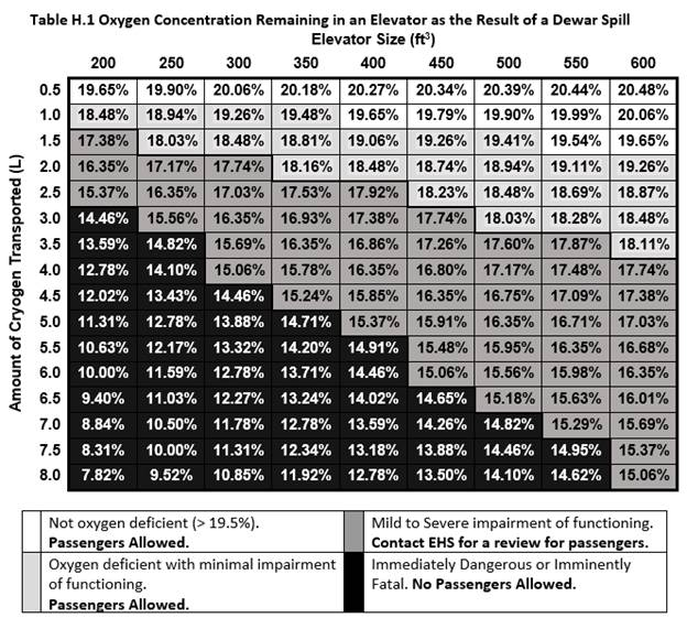
- For low pressure dewars, a risk assessment should be performed to determine the oxygen deficiency hazard in the elevator space in case the dewar spills or a passenger is trapped in the elevator with the evaporating cryogen for a prolonged period.
- Table H.1 provides guidance on when it is appropriate to contact EHS for a review to determine whether it is safe for passengers to accompany the dewar. If the oxygen level in the elevator could fall below 15% in the case that the dewar is spilled, passengers are not allowed to accompany the dewar due to the immediate danger to their life and health in case of a spill.
- It is always safer not to ride in an elevator with a cryogenic liquid dewar.
Whenever a cryogenic liquid cylinder or a low pressure dewar is being transported in an elevator without passengers, a chain must be used to rope off the elevator entrance and a clearly visible sign must be posted to warn others not to enter the elevator while the cylinder or dewar is present. Once the cylinder or dewar reaches its destination, the person transporting the dewar or cylinder may remove it from the elevator, take down the chain and sign, and return the elevator to normal service. Contact your building manager to have chains and signs installed in elevators that are used to transport cryogenic liquids.
The minimum concentration of oxygen left in an elevator following a liquid nitrogen spill can be calculated based on the amount of liquid nitrogen spilled and the volume of the elevator. A simplified equation is given below as a quick means to estimate oxygen concentrations in a given elevator.
where C is the final oxygen concentration in percent by volume, L is the amount of liquid nitrogen spilled in liters, and V is the volume of the elevator in cubic feet.

b. Cryogen Transport in Vehicles
Table H.2 Self-Transport of Cryogenic Liquids Guidelines
| Type of Container | Self-Transport Guidelines |
| Pressurized Cylinders | Self-transport by vehicle not allowed. |
| More than 1L Liquid Cryogen | Self-transport by vehicle must meet full DOT requirements. Call Shipping (x5084 or x4388) for assistance. |
| Less than 1L Liquid Cryogen | Follow General Requirements Below |
| Dry/Vapor Shipping Containers | Follow General Requirements Below |
General Requirements:
- Look for a viable alternative, such as shipping services. It is not recommended for researchers to transport cryogenic materials by vehicle.
- If no viable alternative exists, you will need to be a fully authorized worker on an approved WPC activity that includes the hazard “Transporting Cryogens by foot or by vehicle.” If your activity does not include this hazard, contact your Activity Lead.
- Recommended: Take EHS0657, Self-Transporting Haz Mat.
- Complete EHS0170, Cryogen Safety.
- Package materials in a double-walled, vacuum jacketed vessel, with outer packaging that has sufficient cushioning and absorbent materials to protect the inner vessel(s) from damage.
- Mark the outside of the packaging with the owner’s information, including a valid phone number.
- Place the container upright in an open area such as the open bed of a truck.
- Secure the container against movement and tipping.
- Under no circumstances is a cryogenic liquid cylinder or low pressure dewar to be stored or transported in the closed cabin or trunk of a vehicle, or on a bus or shuttle. Cryogenic liquid cylinders and dewars must be transported in the open bed of a truck or similar vehicle.
Vendors such as Praxair, Airgas, and Matheson Tri-Gas are responsible for the safe delivery and transportation of large cryogen dewars to LBNL users.
Note: Dry/Vapor Shipping Containers are by far the safest way to transport cryogenically frozen samples. These containers may be transported on the LBNL shuttles. Clearly mark the container as a dry shipper before boarding the shuttle. Contact the Cryogens SME for information on where to find and order dry/vapor shippers.
c. Cryogenic Materials Transport Between and Within Buildings
- Small quantities of liquid nitrogen or liquid argon may be transported in and around buildings in an appropriate low pressure dewar (fitted with a lid) by their carrying handles.
- Do not transport cryogenic liquids in open dewar flasks
- Do not attempt to carry additional items with the dewar, such as books, beverages, samples or tools
- Larger low pressure dewars may come with casters/wheels attached to the bottom, or the dewar may need to be secured to an appropriate dolly or cart.
- Dollies and carts used to transport dewars should keep the dewar as low to the ground as possible
- Do not transport low pressure dewars on the top shelf of a hand cart
- Check the entire route ahead of time to ensure that it is free of obstructions and obstacles which may cause a cart to tip.
- Heavy cryogenic liquid cylinders must be transported with an appropriate cart designed for the specific cylinder model.
- Never roll cryogenic liquid cylinders
- Often, the vendor will deliver the cryogenic liquid cylinder directly to its permanent location and pick it up from there as well – this is the ideal case
- Appropriate PPE is still required when transporting cryogenic liquids around buildings (see Table E.1).
- Before transporting cryogenic liquid cylinders, the user must ensure that all process valves (gas supply, liquid supply, pressure builder, and vent) are closed.
3. Filling Dewar and Cryogenic Liquid Cylinders from a Fill Station
This section is intended for guidance only and is not a substitute for on-the-job training. Each fill station is different, and on-the-job training is required for each individual fill station. Authorization to use one fill station does not authorize a user to operate other fill stations.
Before undertaking any filling operation, the user must know the following information:
- The appropriate points of contact for the fill-station operation.
- Any applicable personal protection equipment.
- The building point-of-contact for bulk ordering of liquid nitrogen/argon.
- The ES&H point-of-contact for notification of events, such as accidental releases.
Generalized Process for Operating a Fill Station
| Step | Action |
| PREPARATION FOR USE | |
| 1 | Check that the oxygen monitor (if applicable) is operational. |
| 2 | Locate flex lines and fill valve away from point of discharge. |
| 3 | Make any connections for fill or vent that are required. |
| 4 | Position the dewar/cylinder for filling. |
| 5 | Put on personal protective equipment (PPE). Wearing safety glasses is required for the open handling of cryogenic liquids. Additional PPE, such as face shield and gloves, may also be required. PPE requirements depend on the specific system design and operation. |
| FILLING | |
| Caution: Safe use of this system requires 100% manned operation. Operators should not leave the area with a valve either in the open or partially open position. | |
| 6* | When necessary, precool the cryogen line by opening the bypass valve and allowing flow until the supply line is adequately precooled. This may be evidenced by frost on the valve or piping and components. Do not leave the area during line precool. The line is precooled in an effort to minimize the quantity of nitrogen gas that will be vented into the laboratory air space during the filling process. |
| 7* | Close the bypass valve at this time. The line should be adequately precooled so that when the fill valve is opened, liquid-phase nitrogen (or a minimum of gas phase) will flow. |
| 8 | Slowly open the fill valve. You should be able to hear the cryogen flowing through the line and into the dewar/cylinder. Do not leave the area during the filling operation. |
| SHUTDOWN | |
| 9 | When the dewar/cylinder is full, close the fill valve and ensure that both valves are in the fully closed position. |
| 10 | Vent off any residual pressure, then disconnect any connections made and remove the dewar/cylinder from the fill station. |
*Not all fill stations include a bypass line to precool the lines.
NOTE: Appendix F contains some useful calculations that can be used to assess the risk of asphyxiation when using a fill station indoors.
Work Process I. First Aid for Cryogen Contact
Skin contact with either cryogenic liquids or with uninsulated materials at cryogenic temperatures can cause rapid burns. Often, burns from direct contact with cryogenic liquids are not accompanied by pain but by a feeling of numbness and cold. The affected area may not hurt until it thaws considerably. Contact with materials at cryogenic temperatures can instantly freeze any water near the surface of the skin and cause it to stick to the cold material, in addition to causing burns, which may tear the flesh when it is removed. The eyes are especially susceptible to cryogenic damage and can suffer irreparable harm from direct contact with a cryogenic liquid splash. Even vapors that are near cryogenic temperatures can damage the eyes.
Large exposures to cryogenic liquid or cryogenically cold vapor may induce hypothermia, wherein a person’s core body temperature drops to dangerous levels. If the body is not warmed, heart and respiratory failure can result, potentially leading to death.
In case of skin contact:
- If the affected area is extensive, the contact with cryogen or a super-cooled surface was prolonged, skin has been torn from freezing to a cold surface, or if the victim is in distress call x7911 from any main site land line, 911 from a cell phone, or use the local emergency line from off-site locations.
- Thaw the affected area with room temperature (not hot) water.
- If it can be accomplished, dip the burn gently into a bath for 15-30 minutes rather than pouring water over it
- Do not apply dry heat
- Do not massage or rub the area to try to increase circulation
- Loosen any clothing or PPE which might reduce blood flow to the area.
- Watch for signs of shock – cold sweating; paleness; rapid breathing and pulse; or nausea with or without vomiting. If any signs appear, immediately call emergency services, take the victim to a warm place, lie them down, and elevate the feet.
- If blisters appear, the burn will require medical attention. For more severe cases, call x7911, 911 from a cell phone, or a local emergency line. Otherwise, take the victim to seek medical attention as soon as possible and report the incident to the victim’s Activity Lead and Supervisor.
- Cryogenic burns are very painful as they begin to thaw. Aim to thaw the affected area slowly so that medical attention arrives before thawing is complete.
- Infection is a serious concern with cryogenic burns. If the burn is thawed before medical attention is received, cover the area loosely with sterile dressings.
In case of eye contact with cryogen or extremely cold vapor:
- Remove the worker from the source.
- Open eyes wide to facilitate evaporation.
- Immediately call x7911 from any main site land line, 911 from a cell phone, or use the local emergency line from off-site locations.
- Flush the eyes with lukewarm but not hot water for 15 minutes to warm the tissue.
- Do not delay medical attention, as cryogen burns to the eyes can lead to permanent damage and loss of vision; have someone else call while you assist the employee.
In case of hypothermia:
Symptoms of hypothermia include: shivering, dizziness, nausea, fast breathing, confusion, lack of coordination, trouble speaking, fatigue and rapid pulse. In more severe cases, breathing may be slow and shallow and the pulse may be weak.
- If hypothermia is suspected, immediately call emergency services at x7911 from the main site, 911 from a cell phone, or use the local emergency line.
- If the area is still cold, take the victim to a warm area, remove any wet and/or cold clothes, and cover the victim with copious blankets or garments to warm them up.
- Do not move the victim more than is absolutely necessary.
- Do not give the victim anything by mouth.
- Do not apply hot water or direct heat.
- Do not apply heat to the arms or legs.
Work Process J. Waste Disposal
LBNL staff and affiliates must not:
- Dump liquid cryogens into any drain
- Accumulate liquid cryogens in significant quantities in areas not appropriate for that purpose
Small amounts of excess cryogenic liquid from processes may be collected in an approved dewar flask and left to evaporate inside of a fume hood.
Excess cryogenic liquid in a low pressure dewar may be left to evaporate naturally from the lidded dewar, so long as the room is already approved for storage of such a dewar.
NOTE: Even relatively small quantities can damage equipment or facilities and can crack floor tiles, damage water pipes, and damage electrical insulation on wiring. Also, consider the hazard presented by the boil-off gas when any significant quantities of a cryogenic liquid are released. Do not pour cryogenic liquid onto floors, onto surfaces inside fume hoods, into any buckets or containers not approved for cryogenic liquid storage, or into any sinks or drains.
Contact LBNL Waste Management for assistance in determining the best way to dispose of cryogenic liquids.
Work Process K. Reporting Incidents: ES&H Documentation and Reporting/Notification
1. Requirements
LBNL staff and affiliates must apply the requirements for pressure safety aspects of a cryogenic-liquid-handling system as stated in the Chapter 7 Pressure Safety.
For LBNL designed and assembled systems, the system owner must compile a data package according to the requirements in Chapter 7 Pressure Safety.
Any significant accidental releases must be reported to the appropriate supervisor or work lead. Notification through an emergency and non-emergency hotline may be appropriate, depending on the severity of the release. Any personnel in the vicinity who could be exposed to the hazards of the release must be notified. A predetermined point of contact, such as the person responsible for ordering the product, could also be useful because the schedule for re-ordering may be affected by large-volume releases.
NOTE: Incidents that are reported to the non-emergency hotline are useful in tracking and analyzing accident and failure scenarios, determining trends, and changing engineering configurations or procedures.
Results of qualitative and quantitative risk assessments will be stored in a database for future reference and for use in establishing Work Planning and Control Activities when required. Risk Assessments conducted in the field by persons other than the SME must be emailed to the Cryogens SME.
2. Guidance
Commercial (off-the-shelf) vessels which are intended and engineered for cryogenic service may be used as is, but available owner or operator manuals should be retained for reference as part of the system data package.
29.6 References
Source Requirements Documents
- 8 CCR Chapter 4, Subchapter 7, General Industry Safety Orders
- 10 CFR 851, Worker Safety and Health Program
- ANSI/ASME B31.3, Process Piping
- ASME Section VIII Division 1, Pressure Vessels
- CGA P-12, Safe Handling of Cryogenic Liquids
- Compressed Gas Association, Pamphlet P-12, Safe Handling of Cryogenic Liquids
- Compressed Gas Association, Pamphlet P-12, Safe Handling of Cryogenic Liquids, 6.7
- NFPA 45 Standard on Fire Protection for Laboratories Using Chemicals, Chapter 10, Compressed and Liquefied Gases
- NFPA 55, Standard for the Storage, Use, and Handling of Compressed Gases and Cryogenic Liquids in Portable and Stationary Containers, Cylinders, and Tanks
- Public Law 91-596
- International Fire Code (IFC)
Implementing Documents
ES&H Manual, Chapter 7, Pressure Safety
Related Documents
- British Cryogenics Council, Safety Panel, Cryogenics Safety Manual
- Edeskuty, F. J., and W. F. Stewart, “Safety in the Handling of Cryogenic Fluids,” 1996, Plenum Press
- Timmerhaus, K. D., and T. M. Flynn, “Cryogenic Process Engineering,” 1989, Plenum Press
29.7 Appendices
Appendix A: Common Cryogen Systems
Table of Contents:
- Low Pressure Dewars
- Dewar Flasks
- Pressurized Cryogenic Liquid Cylinders
- Cryogen Filling Stations
- Cryomagnets
- Cryostats
- Cryogenic Storage and Shippers
Low Pressure Dewars
Image Copyright 2017 Chart Industries, Inc. Used with permission, all rights reserved.

Low pressure dewars are only intended for short-term storage of cryogenic liquids, at maximum several days. They are typically only filled on demand. These systems consist of a vacuum jacketed cryogen reservoir, which is usually made of a silvered glass, with an outer casing of aluminum or steel. A loose fitting plug style cap, usually made mostly of foamed plastic for better insulating properties, is used to allow for the release of boil-off gases so that the pressure inside the dewar does not exceed atmospheric pressure, while also keeping air out to avoid condensation of liquid oxygen. In general, these dewars are small and easy to transport. The smallest can be carried with handles, while the larger models may come with wheels mounted to the bottom, or a small cart or dolly may be needed. The vacuum space around the cryogen reservoir is equipped with a pressure relief valve in case the inner reservoir cracks and allows cryogen into the vacuum space. In that scenario, pressure might build up inside the vacuum space and rupture the dewar, so instead it is safely vented through a relief valve.
It is important to inspect all dewars carefully before use. Check that no corrosion is visible on the outside of the casing. The safety valve should be intact and should not be bypassed or defeated in any way. The plug cap should slide easily into the neck of the dewar and should not seal or become stuck.
During use, the dewar should not form ice on the outside of the aluminum casing or on the cap. If ice does form on the outside of the dewar, it indicates that the dewar may have lost vacuum and may no longer be insulating enough for cryogenic liquid storage. Additionally, if there are cracks in the inner silvered glass reservoir, liquid cryogen may get into the vacuum space and upon warming of the dewar the entire vessel can explode from the expanding cryogen. If the foamed plug portion of the cap breaks off or is removed, then the remaining plastic cap will build up ice due to the lack of insulation between the plastic and the cryogenic reservoir. Without proper insulation, the dewar may be allowing more gas to escape into the room than was accounted for in the initial risk assessment for the use of cryogen in that particular room. In the case of a damaged dewar, it is possible that the cryogen reservoir may shatter violently and unexpectedly due to the large amount of stored energy in the pressure differential created by the vacuum jacket.
If there is any sign of damage or loss of insulation, the dewar must immediately be taken out of service and marked as defective to prevent its further use. Only individuals who are trained, qualified and experienced in the repair of this type of vessel should ever attempt to repair a damaged dewar.
Note: Consumer products such as Thermos® bottles and vacuum flasks are not approved for cryogenic applications. Although the container itself may hold cryogenic liquid in an adequate manner, the lid, even when loosely applied, does not allow for proper venting of boil-off gases and may lead to an explosion of the pressurized vessel. These containers must never be used for cryogenic liquids, even for a short period of time. Before purchasing any dewars or “vacuum flasks” for use with cryogenic liquids, check the specifications or call the manufacturer to confirm that it is intended for cryogenic liquid service.
Dewar Flasks
Images copyright © Day-Impex Ltd. All rights reserved.

These open containers are designed to hold cryogen for relatively short periods of time to accomplish various laboratory operations. Many dewar flasks come with a foam, loose fitting or vented lid that can reduce the evaporation rate of cryogen inside without allowing for the buildup of pressure inside the vessel. Depending on whether there is a lid, the type of lid, and the size of the container, dewar flasks may hold liquid cryogen for anywhere from a few hours to a few days. These units can be used to cool the trap on a vacuum line, dip materials for quick freezing, cool entire reaction vessels, etc. Dewar flasks are made of double-layered glass, evacuated between the layers, with a protective aluminum or steel casing. These are the most fragile of all cryogenic liquid containers, but are unlikely to implode without impact or damage to the glass. However, when they do shatter the process is quite energetic and fragments of glass may be ejected from the top opening of the flask at high speed. Wrapping the dewar flask with plastic or tape with the intention of preventing or mitigating an implosion event has not been proven to be effective at preventing or containing implosion events, but is not known to cause any harm. If the unit is wrapped, the wrapping must not cover the warnings printed on the outside of the flask, or else a new warning label must be printed and affixed to the outside of the unit. Because these units tend to accumulate condensation, the label should be waterproof. A typical warning statement is as follows:
WARNING! Vacuum flask – may shatter unexpectedly, may cause injury. Wear safety glasses.
The risk of implosion cannot be completely mitigated, but there are some practices that can reduce the risk somewhat:
- Before ever using a dewar flask for the first time, unpack and inspect it for any cracks, scratches, or chips. Tiny cracks or scratches in the glass will expand over time and eventually the glass will lose integrity and shatter.
- Some manufacturers instruct the user to wash the inside of the dewar flask gently with soapy water, rinse it with deionized or distilled water, and dry it thoroughly with a soft, lint free material before the first use. This removes any dust, debris or residue from the packaging material. Follow the manufacturer’s instructions.
- Some manufacturers recommend pre-cooling the dewar before filling it completely with cryogenic liquid. This can be done by adding a small amount of cryogen to the flask, swirling it, and letting it stand for 5-10 minutes before filling the dewar the rest of the way.
- Before each and every use of the dewar flask, inspect it for cracks, chips or scratches.
- Ensure that the dewar flask is completely dry before filling, as water trapped within miniscule cracks and scratches which subsequently freezes (and expands) can cause the dewar to shatter.
- Handle dewar flasks with care. Place them only on flat, level surfaces to prevent them from tipping over. Take particular care not to drop dewar flasks or allow them to fall any distance.
- Do not use any tools to scrape the inner glass of the dewar flask. Do not use any hard tools to prod at contents inside a dewar flask. Do not drop objects into a dewar flask; place them gently.
- When using a dewar flask to cool a vacuum trap, it is recommended to use a blast shield in front of the trap to protect the researcher from flying shrapnel in case the vacuum trap explodes.
While using the dewar flask, it should not form ice on the outside casing, although condensation is normal. If any damage is evident in the form of cracks, scratches, chips or otherwise, immediately remove the dewar flask from service. Do not attempt to repair a damaged dewar flask.
Note: Consumer products such as Thermos® bottles and vacuum flasks are not approved for cryogenic applications. Although the container itself may hold cryogenic liquid in an adequate manner, the lid, even when loosely applied, does not allow for proper venting of boil-off gases and may lead to an explosion of the pressurized vessel. These containers must never be used for cryogenic liquids, even for a short period of time. Before purchasing any dewars or “vacuum flasks” for use with cryogenic liquids, check the specifications or call the manufacturer to confirm that it is intended for cryogenic liquid service.
Pressurized Cryogenic Liquid Cylinders
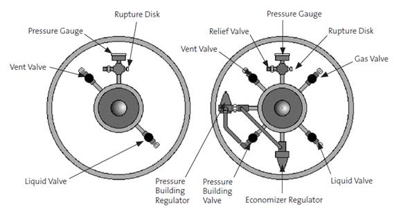
These units are intended for longer-term storage of cryogenic liquids, on the order of a few weeks to a few months. They typically operate either at pressures of about 22psig for liquid use, or at higher pressures of 230 or 350psig for gas use. The 22psig cylinders tend to be better insulated and are able to hold cryogenic liquid for a longer period of time, but do not vaporize cryogen at a sufficient rate for significant gas withdrawal. The lower pressure makes withdrawal of liquid cryogen safer than if the cylinder were operating at 230 or 350psig. Attempting to withdraw liquid cryogen from a 230 or 350psig cylinder is potentially very dangerous and highly discouraged. The high pressure cylinders are designed to ensure that the cylinder has an appreciable evaporation rate and sufficient pressure for gas operations, which often require delivery pressures greater than 100psig and/or high flow rates.
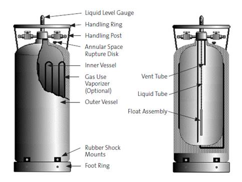
The design of cryogenic liquid cylinders is necessarily more complex and robust than the atmospheric pressure dewars (see diagrams above) due to the large pressures involved. When extracting cryogenic liquid from the cylinder, the vapor pressure of the cryogen causes the liquid to flow up through a tube and out the liquid valve. Some cylinders may come with a liquid valve built in, while others may require a tube to be inserted into the cylinder, often called a “stinger”. The cryogenic liquid will be released at high pressure because of the pressure inside the cylinder. Use a lower pressure (22psig) cylinder for liquid service to minimize the risks from high pressure cryogen streams. See Work Processes D, E and H for more information on engineering controls, required PPE, and good laboratory practices.
Gas is extracted through a separate valve, which draws from the headspace of the cylinder, above the liquid level. This gas will be just barely warmer than the boiling point of the cryogenic liquid and still poses a significant hazard for burns and frostbite. The high pressure (230 or 350psig) cylinders are usually preferred for gas use because they can deliver higher flow rates, but for applications which require only low flow rates and low pressures, the low pressure cylinders may be used. In order to achieve even higher flow rates, many cryogen cylinders are equipped with a gas use vaporizer, which directs cryogenic liquid through tubing outside of the normal liquid reservoir to vaporize it for immediate use as a gas (see the diagram above). Where necessary, a cryogen cylinder can also be equipped with a pressure builder to allow the user to manually increase the pressure inside the cylinder for an application that requires it. Conversely, where pressure increases more rapidly due to cryogen evaporation than the gas is used, some cylinders have an economizer installed to direct the excess pressure inside the cylinder to the gas use valve instead of using the gas use vaporizer, reducing the amount of cryogen lost to venting through the pressure relief valve.
Before withdrawing gas from a cryogenic liquid cylinder, it is important to verify that the gas use valve is connected and not the liquid valve.
NOTE: Cryogenic liquid cylinders are only intended to be operated in a fully upright position. Never attempt to operate a tilted cylinder (e.g., while on a cart), and never lay a cryogenic liquid cylinder on its side.
Cryogenic liquid cylinders will always have a pressure gauge, a pressure relief valve and a rupture disk installed to prevent over-pressurization of the cylinder. The pressure relief valve and rupture disk must be able to withstand cryogenic temperatures without losing performance or altering the pressure at which they vent. A vent valve provides another means of reducing the pressure inside the cylinder, but manually.
Before filling a cryogenic liquid cylinder, it is important to inspect the cylinder for damage and to verify that the cylinder is approved and designed for the particular cryogen service. For example, liquid helium, liquid oxygen and liquid hydrogen in particular all have very specific requirements for the design of the cylinders (see Appendices B, C and D); these gases should never be filled into a cylinder that is not of the correct design. Some cryogenic gases are even dangerously incompatible, such as LH2 and LOx – an explosive combination. Most cryogenic liquid cylinders will indicate what type of gas they are meant to hold, either by way of a label with the gas identification, or with a clearly marked tag. Never fill a cryogenic liquid cylinder with a different gas than the one for which it is marked.
Common signs of damage on a cryogenic liquid cylinder include rust or corrosion on any of the parts, dents on the external surfaces, tubing and valves that are bent and should be straight, missing pressure relief valves, a burst rupture disk, or a pressure gauge that reads greater than ambient pressure when the cylinder is empty. Never fill a cylinder which shows any sign of damage. It is also important to watch the cylinder once it is filled for any sign of abnormal operation. When withdrawing large flow rates of gas for prolonged periods of time, some ice formation is normal around the gas valve and fittings and sometimes on the sides of the cylinder. Some ice may also build up on the pressure relief valve if the cylinder is venting frequently. However, any ice buildup that cannot be explained through normal operation of the cylinder may be a sign of a defective cylinder. If any signs of damage are observed, or the cylinder behaves abnormally in any way, take the cylinder out of service immediately and contact the manufacturer of the cylinder or the vendor that supplied it. Only individuals who are trained, qualified and experienced in the repair of this type of vessel should ever attempt to repair a damaged cryogenic liquid cylinder.
In many cases, a vendor such as Praxair, Airgas or Matheson will deliver a cryogenic cylinder pre-filled, and pick up the empty cylinder. The vendor is then responsible for inspecting the cylinders before filling and ensuring safe operation. However, it is still important to watch for any unusual signs during operation of the cylinder, such as abnormal ice build-up. If anything seems abnormal, call the vendor immediately to have them pick up the cylinder, and be sure to inform the vendor that you suspect a defect.
Troubleshooting a Problem Cylinder
|
|
|
|
Cylinder vents too frequently |
|
|
Ice on valves of cylinder |
|
|
Ice on sides of cylinder |
|
|
Liquid dripping from any of the valves |
|
|
Pressure above maximum, but not venting |
The most likely cause is that the regulator on the cylinder is out of adjustment or defective – if you have another regulator attached to the gas service valve you can check to see if they agree, but the cylinder should still be taken out of service immediately and either returned to the vendor or else repaired by the manufacturer or a trained, qualified and experienced individual. |
Cryogen Filling Stations
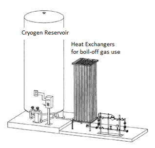
Cryogen filling stations are a long-term solution to frequent cryogenic liquid needs. Facilities and the EHS division work with a vendor to design and install a unit such as the one pictured above. The tank can be filled from a large cryogen transport vehicle, and both gas and liquid cryogen can be withdrawn from the system. These systems are most commonly used for liquid nitrogen and can be used to fill either a low pressure dewar or a cryogenic liquid cylinder. Often, the natural boil-off gas is also used (e.g., “house nitrogen”) after passing it through a heat exchanger to warm it to room temperature. In-depth on-the-job training is required for each individual filling station, as they are all unique installations. More information on cryogen filling stations and how to use them can be found in Work Process H.
Cryomagnets
Generally, cryomagnets are used for NMR and MRI applications, though they are also used in particle accelerators, some mass spectrometers, and for magnetic separations. The cryomagnet consists of a coil of wire, just like a standard electromagnet, but the wire is made of a material which is superconducting at very low (i.e., cryogenic) temperatures. Below a certain temperature threshold (usually ~10K), the wire begins to conduct current with insignificant resistance, allowing much higher currents, and thus the magnet can attain much higher field strengths, up to 25-30 Tesla. For comparison, a standard refrigerator or bulletin board magnet has a field strength of approximately 5/1000ths of one Tesla, and high-strength rare-earth magnets, such as neodymium magnets, have a field strength at their surface of roughly 1.25 Tesla. This document does not cover the hazards associated with high strength magnetic fields; information on the nature of cryomagnets is provided solely for context.
As the name implies, cryomagnets require cryogenic temperatures to operate. While a few high-temperature superconductors do exist, most superconductors require temperatures below about 10K (-263°C or -440°F) to exhibit superconducting properties; above that temperature, they conduct electricity like any other normal material, with normal resistance. This presents a risk because if the cryomagnet is allowed to warm to above ~10K it will lose its superconductivity and will immediately begin to produce significant heat as its resistance returns to normal. This is accompanied by a “magnet quench”, in which all of the cryogenic liquid that was being used to cool the magnet is rapidly boiled off by the heat produced by the coil. Since cryomagnets typically contain large volumes of both liquid helium and liquid nitrogen, this can cause severe and rapid oxygen depletion in the room, reducing oxygen levels to well below concentrations that can be fatal in a short period of time. These systems usually necessitate engineering controls such as oxygen monitoring, as described in Work Process D.
Magnet quenches are rare (at least one system at LBNL has gone for over 10 years without a single quench), but they are more likely to occur during maintenance of the system and filling of the cryogen reservoirs. Magnet quenches can also occur if the level of cryogen in the system drops too low to sustain superconducting temperatures, so it is important to follow the manufacturer’s instructions for the filling schedule of the cryogen reservoirs.
Only trained personnel should ever attempt to fill the reservoirs or perform maintenance on a cryomagnet system.
Cryostats
A cryostat is a system designed to maintain a cryogenic temperature in some experimental volume, device or sample chamber. There are multiple types of cryostats, but they all operate in roughly the same way: a cryogenic liquid is used, with the aid of heat exchangers, to cool the device of interest and keep it at a stable, cryogenic temperature.
The two most common types of cryostat are Continuous Flow Cryostats and Bath Cryostats. In a Continuous Flow Cryostat, a cryogenic liquid is flowed through a heat exchanger assembly and then allowed to warm, vaporize and vent into the atmosphere. The tube that carries the cryogen flow is typically vacuum shielded to keep the cryogen cold on its way to the heat exchanger, and is open to atmosphere past the heat exchanger such that the line is never pressurized. The cryogenic liquid is typically extracted from a cryogenic liquid cylinder.
A Bath Cryostat is the simplest type of cryostat and typically consists of a small reservoir of cryogenic liquid that is brought into thermal contact with the device of interest. The bath is allowed to vaporize into the atmosphere as it cools the device, and must be replenished either from a liquid flow from a cryogenic liquid cylinder, or by manually pouring more cryogenic liquid into the bath from a low pressure dewar.
Commercially available cryostat systems are available where the user need only connect a full cryogenic liquid cylinder to the device. When using a commercially available cryostat, users must follow all manufacturer’s instructions and safety precautions, in addition to the requirements in this document.
NOTE: A risk assessment of the oxygen deficiency hazard is still necessary, even with a commercially available cryostat system.
Cryogenic Storage and Shippers
Vacuum-jacketed vessels are available for both storage and shipping of cryogenically frozen samples. Vessels for storage and shipping differ somewhat, but both are constructed similarly to the low pressure dewars described in (i).
Cryogenic Storage Vessels are essentially a wide mouth version of low pressure dewars but also include a rack in which samples can be loaded and lowered into the cryogenic liquid. The vessel can be filled just like a low pressure dewar. The rack is designed to fit the specific storage vessel and can be easily lifted out. Users should wear cryogen gloves when inserting or removing samples. See Work Process H, section (i) for safe laboratory practices that apply when loading samples into a cryogen storage vessel and for removing closed containers from cryogenic liquid.
Cryogenic Dry/Vapor Shippers look much like their storage counterparts, but differ in one major way: these shipping containers only hold cryogenic liquid trapped within an absorbent material so that the cryogenic temperature is maintained inside the vessel, but there is no potential for a spill during transportation and shipping. Follow all manufacturer’s instructions for loading the shipper, adding cryogenic liquid if necessary, and packaging the vessel for transport or storage.
Anyone planning to self-transport a Cryogenic Dry/Vapor Shipper must follow the guidelines set out in Work Process H, section (ii). This includes:
- Being an approved worker on a WPC activity with the hazard “Transporting Cryogens by foot or by vehicle.”
- Packaging the vessel in a sturdy box with cushioning and absorbent materials to protect the Shipper from damage.
- Marking the outside of the package with the owner’s information, including a valid phone number.
- Never transporting such a Shipper in the cabin or trunk of a vehicle or on a shuttle bus (set the container in the open bed of a truck instead).
- Securing the container against movement during transport.
Before purchasing or shipping a Cryogen Dry/Vapor Shipper, please contact the Cryogens SME for additional assistance and to have the vessel approved. See Work Process H section (ii) for more information on transport and shipping.
Before use, these vessels should be inspected for signs of damage, much like any low pressure dewar. In both cases, the vacuum jacket can fail and potentially allow cryogenic liquid to enter the vacuum space. Generally, the pressure relief valve is on the bottom of this type of vessel. After loading the vessel with cryogenic liquid, ice should not form on the outside of the aluminum casing – ice formation is a clear sign that the vacuum jacket has failed. If any signs of damage are evident (e.g., dents of the casing, scratches inside the silvered glass cryogen reservoir, corrosion, missing or damaged pressure relief valve, ice formation, etc.) the vessel should be taken out of service and marked as defective.
Only individuals who are trained, qualified and experienced in the repair of this type of vessel should ever attempt to repair a damaged cryogenic storage vessel or shipper.
Appendix B: An Overview of the ODH Calculator Model
An Overview of the ODH Calculator
The Oxygen Deficiency Hazard (ODH) calculator is a simple tool that allows rapid evaluation of the oxygen deficiency hazard of a room using conservative assumptions. It is well suited to simple cryogenic systems including the storage and filling of dewars, the use of freezers with cryogenic liquid backup systems, and the use of cryogenic liquids to cool cryomagnets. More complex systems will require a quantitative approach, as discussed in Step 6 below.
| Understanding Oxygen-Deficiency Calculator Results and Limitations |
| If there is no oxygen deficiency hazard for any routine condition and the ODH hazard class is zero, no further action is required. |
| If either the ODH hazard is not zero or an oxygen deficiency hazard (oxygen level drops below 19.5%) is possible for any routine operation, the ODH of the room must be analyzed by an industrial hygienist, and further engineering and/or administrative controls may be required. |
| The ODH calculator is not for use with plumbed liquid nitrogen supplies; the ODH of these locations must be evaluated by other methods. (Contact SME for more information.) |
| If the room has activities that do not map onto the scenarios in the ODH calculator, the ODH must be determined by other methods. (Contact SME for more information.) |
| Explanation of Terms Used in the ODH Calculator | |
| Terms | Description |
| Building, room, fume hood, room dimensions | Self-explanatory. Units are in feet. |
| Total volume of cryogens | Self-explanatory. Units are in liters. Includes the volume of all storage dewars plus any other device that contains cryogens, e.g., cryomagnets, freezers, cold traps. Note that all cryogens are assumed to be liquid helium with an expansion factor of 757:1, which is slightly conservative compared with that of liquid nitrogen (696:1) and slightly non-conservative with respect to that of liquid argon (847:1). |
| Largest storage dewar | Self-explanatory. Units are in liters. Largest dewar by volume in the room can be a storage dewar, freezer, cryomagnet, etc. |
| Largest transfer dewar | Transfer dewar is a smaller dewar that is filled from a storage dewar and is used to transfer cryogen to another location. These are typically 4 L dewars, but larger dewars for cryostats are also to be included here. Units are in liters. |
| Largest volume used routinely | Largest volume of cryogen that is used in an open system. This includes open dewars, and dewars used with cryostreams, cryostats, etc. Units are in liters. |
| Number of freezers with LN2 backup | Self-explanatory. If the freezer is smaller than 13 ft3, include it in the 13 ft3 box. If it is much larger than 25 ft3, enter the volume of the freezer divided by 25 (this quotient needs to be multiplied by the number of large freezers, of course). |
| LN2 in cryomagnet | Self-explanatory: the volume of the LN2 jacket, if present, in liters. |
| LHe in cryomagnet | Self-explanatory: the volume of LHe in the cryomagnet dewar, in liters. |
| Energy of cryomagnet | Energy stored in the cryomagnet in kilojoules. If unknown, just enter a zero in this box. The magnet will be assumed to volatilize all of the stored LHe in a quench. |
ODH Calculator Model
The Oxygen Deficiency Hazard calculator uses the Fermilab probabilistic methodology to determine the oxygen deficiency hazard (Fermilab ES&H Manual 5064). For each scenario, the value of %O2 is determined using the equation:
The probability of death upon exposure to this concentration of oxygen is calculated using the Fermilab methodology. Then finally, the probability of death for each scenario is multiplied by the probability of that scenario occurring, and the products for all scenarios are summed to give an overall probability of death resulting from cryogen use in this room. The ODH class is assigned using the values in Table C.2, below. Although this model uses a formula for the %O2 in the absence of ventilation for the probabilistic model, there is an implicit assumption of one air exchange per hour.
ODH Hazard Classification
| ODH Class | Fatalities per hour from model |
| 0 | <10-7 |
| 1 | <10-5 and >10-7 |
| 2 | <10-3 and >10-5 |
| 3 | >10-3 |
Scenarios Considered in ODH Calculator Model
| Possible Scenarios – Routine Operations (all have a probability of 1 per hour) | |
| Scenario | Description |
| Storage of cryogen | Release of all stored cryogen is assumed to be 5% per day. The reported values are 2% per day for typical storage dewars, but the 5% value is used to account for the fact that some dewars, especially high-pressure storage dewars, cryomagnets, and cryogenically cooled traps, have a larger release rate. All cryogen is assumed to be liquid helium with an expansion ratio of 757, which is slightly conservative compared with that of liquid nitrogen (680). But the liquid helium expansion ratio has the advantage that less data needs to be entered since only cryomagnets, not different types of cryogens, are entered into the model. |
| Routine work | Work with cryogen that will actively be generating gas includes such tasks as working in open dewars (crystal mounting) or using liquid nitrogen to actively cool experiments (cryostream). All of the cryogen in the dewar is assumed to be used within one hour. Cryogen is assumed to be liquid helium for the purpose of expansion ratio. |
| Filling transfer dewars | A smaller, transfer dewar is filled from a larger, storage dewar. Loss rate is assumed to be 10%. |
| Refilling cryomagnet | When a cryomagnet has its liquid helium and liquid nitrogen reservoirs refilled, loss rate is assumed to be 10%. Both dewars are assumed to be filled at the same time. |
| Cool-down of cryomagnet | A cryomagnet is initially cooled with liquid nitrogen then cooled with liquid helium, which may be in separate reservoirs. All operations are assumed to be finished within one hour. The liquid nitrogen loss rate is 20% of the volume of the reservoir, and the liquid helium loss rate is 50% of the volume of the reservoir. Based on cool down of a Quantum Designs Magnetic Property Measurement System on 10/26/09, 76 L of LHe is needed to cool and fill a 56 L reservoir. LN2 loss rate is an estimate and is probably too high since liquid nitrogen has a high heat of vaporization. |
| Possible Scenarios – Non-Routine Scenarios | |
| Power Outage | The assumption is that power is lost to a building (especially a bio lab containing freezers with liquid nitrogen backup) for 8 hrs before someone notices (this may not be a very plausible scenario). All of the nitrogen evolved from storage dewars and the nitrogen used to cool down the freezers evaporates into the lab. The rate of liquid nitrogen use for freezer backup was obtained from Fisher and So-Low and is 7 lbs/hr and 11.6 lbs/hr for 13 cu ft and 25 cu ft –80 °C freezers, respectively. The assumption is that this event happens once every two years, which is grossly conservative; this scenario is not plausible in the absence of an earthquake (p=5.7×10⁻⁵/hr). |
| Transfer dewar spill | Transfer dewar is knocked over and all cryogen evaporates into room. The assumption is that this event happens approximately four times per year (p=4.6×10⁻⁴/hr). |
| Complete failure of dewar | Dewar fails (valve is snapped off) and all cryogen is lost into room and evaporates in an hour. Failure rate is from Fermilab for failure of vacuum jacket of dewars (p=1×10⁻⁶/hr). This is in good agreement with our observations of one failure in 10 years among ~10 dewars in the 70/70A complex (p=1.14×10⁻⁶/hr). The oxygen level is calculated for the largest dewar that can fail, and the probability is multiplied by the total volume of stored cryogen divided by the volume largest dewar to account for the probability of other dewars failing. |
| Magnet quench | Cryomagnet ceases to be superconducting and boils off helium equivalent to the stored energy (heat of vaporization 0.0845 kJ/mol). If the stored energy is unknown, all of the helium in the jacket is assumed to be vaporized. Vaporization of liquid nitrogen is not an issue due to its much higher heat of vaporization (5.6 kJ/mol), which means that 66 times less nitrogen would be released than helium. Failure rate is from Fermilab (p=1×10⁻⁶/hr). |
Appendix C: Liquid Helium
Liquid helium is the coldest of all the cryogens, with a boiling point of approximately 4K (-268.9°C or -452.1°F). This incredibly low temperature is cold enough to solidify air (the nitrogen and oxygen, not just the water) into a kind of ice. Because of this, it is far more common to accumulate solid obstructions in the valves of pressurized liquid helium cylinders than with nitrogen or argon. Users of liquid helium cylinders must exercise extreme care to prevent ice obstructions, which can cause liquid helium vessels to over-pressurize rapidly.
At the ALS, this exact situation occurred. A liquid helium cylinder was in use at the ALS, and a user failed to close one of the valves when finished with their operation. Nothing seemed amiss until a few days later, when another user went to withdraw liquid from the cylinder. This particular cylinder required that a long metal tube, a “stinger”, be inserted through the top of the cylinder all the way to the bottom of the cryogenic liquid reservoir in order to withdraw liquid. But the user found that the tube would not insert all the way; instead, it hit something hard well above the bottom of the reservoir. It turned out that air had entered the cylinder through the valve that was left open, had frozen solid on top of the liquid helium, and formed an impenetrable plug. Had the situation not been discovered and remedied, the cylinder may have exploded as the helium trapped below the plug slowly vaporized and built up pressure in the confined space.
Unlike nitrogen and argon, which are denser as gases than air, helium as a gas is far less dense than air. With liquid nitrogen and liquid argon, the largest danger of asphyxiation is close to the ground, especially in recessed areas. However, with liquid helium the largest danger of asphyxiation is at ceiling level, where the helium gas will accumulate and displace oxygen most rapidly. Therefore, when working with cryogenic helium, users must be aware of what is above them. People on catwalks or ladders will be more quickly affected by a release of helium gas than someone on the ground.
Pressurized liquid helium cylinders are rarely operated at high pressures like liquid nitrogen or liquid argon which come in cylinders with pressures up to 350psig. Instead, most liquid helium cylinders are operated at less than 20psig. Cryogenic liquid cylinders used for helium sometimes have more complex insulation systems to minimize loss rates, which can be quite high for liquid helium. Cryogenic liquid cylinders intended for use with liquid nitrogen or liquid argon are likely to be completely unsuitable for containing liquid helium.
Always check that the cryogenic liquid cylinder is clearly marked for use with helium before attempting to fill it with liquid helium. Follow all manufacturer’s instructions for the cylinder carefully to prevent ice obstructions and over-pressurization of the cylinder. Valve sequencing may be far more complex, even for routine operations, and is incredibly important, as demonstrated by the incident at ALS.
Example of a Relatively Simple Valve Sequence from Air Products:

Appendix D: Liquid Hydrogen
In addition to being one of the coldest cryogenic liquids with a boiling point of only 20K, hydrogen is an extremely flammable material. Hydrogen gas is explosive in air from concentrations as low as 4% by volume. Even if an asphyxiation hazard does not exist from boil-off of hydrogen gas, the atmosphere around the source may still be flammable and/or explosive. The initiation energy for this reaction is also incredibly low, meaning that even a small spark, a static electricity discharge, or a nearby hot material may initiate a hydrogen gas fire or explosion. All equipment used for or near liquid hydrogen operations must therefore be electrically grounded and bonded to reduce the risk of explosion. A hydrogen leak which catches fire will produce a very pale blue, almost invisible flame which is easy to miss and personnel may unknowingly walk into or place a hand into a hydrogen flame.
Because hydrogen is so flammable and readily explosive, extreme care must be taken so that it never comes into contact with air. Liquid hydrogen cylinders should never be used for other cryogenic liquids, and cylinders intended for other cryogenic liquids should never be used for liquid hydrogen. All lines used to transfer hydrogen gas or liquid must be thoroughly purged of air by evacuating the lines and backfilling with inert gas at least three times. Additionally, any pressure relief valves on a liquid hydrogen cylinder must be routed to minimize the risk of creating a flammable or explosive mixture with air. Transfer lines carrying liquid hydrogen are also prone to condensing air and forming oxygen enriched liquid or atmosphere, which only increases the risks of fire or explosion when working with liquid hydrogen. Vacuum insulated transfer lines are thus a necessity with liquid hydrogen.
Unlike nitrogen and argon, which are denser as gases than air, hydrogen as a gas is far less dense than air. With liquid nitrogen and liquid argon, the largest concentrations of released cryogen will be close to the ground, especially in recessed areas. However, with liquid hydrogen the vented gas will accumulate at ceiling level, at the highest point. Hydrogen concentrations can be far greater in vaulted areas of the ceiling or in the open area above a drop ceiling, where room ventilation systems may not flush it out as effectively. These types of features pose a large asphyxiation and fire/explosion hazard.
The inherent dangers of working with liquid hydrogen cannot be overstated. A thorough review by EHS personnel will be needed for any proposed work with cryogenic liquid hydrogen, and all liquid hydrogen systems must comply with Cal/OSHA’s General Industry Safety Orders, Group 20, Article 138.
Appendix E: Liquid Oxygen
Although oxygen is not flammable in itself, it is a strong oxidizer and can cause flammable and combustible materials to catch fire and burn. As discussed throughout this chapter, our atmosphere typically contains about 21% oxygen by volume. This is plenty of oxidizer to burn a wide range of flammable and combustible materials. Liquid oxygen is not only 100% oxygen by volume, but that oxygen is far more concentrated as a liquid than as a gas, since liquid oxygen expands by 860 times when allowed to warm to room temperature. A single drop of liquid oxygen has as many oxygen molecules, and thus as much oxidizing power, as approximately half a liter of air. It should not be surprising, then, that liquid oxygen is capable of causing fires in materials that aren’t normally considered flammable by the layperson, while materials which are known to burn in air will burn far more vigorously in atmospheres with increased oxygen concentration. Some materials may even ignite spontaneously on contact with liquid oxygen or high gaseous oxygen concentrations.
Hair, clothing, oil, grease, kerosene, tar, asphalt, and many plastics and rubbers will all burn readily in oxygen rich environments. In particular, cloth and clothing can trap oxygen gas in the porous weave of the fibers and remain incredibly prone to ignition long after the source of oxygen has been removed. Clothing that has been exposed to liquid oxygen will burn incredibly hot and fast if ignited, and will ignite more easily. All sources of ignition and incompatible materials must be kept away from liquid oxygen operations.
Vessels that contain liquid oxygen must be cleaned to very strict standards to ensure that no hydrocarbon or other incompatible contaminant is present. Oxidation of incompatible materials by liquid oxygen produces significant heat which causes the liquid oxygen to vaporize and expand quickly, potentially leading to the rupture of its container. The construction of a vessel to contain liquid oxygen must also avoid the use of any material which may oxidize or burn on contact with liquid oxygen. This makes liquid oxygen vessels unique in their construction. Liquid oxygen should never be added to any vessel of any type unless it is specifically constructed for use with LOx and has been cleaned according to strict protocols to ensure the complete removal of incompatible contamination.
Unlike every other cryogenic liquid, LOx does not pose an asphyxiation risk. However, at high enough concentrations oxygen may damage the lungs, airways and eyes.
A thorough review by EHS personnel will be required for any proposed work with cryogenic liquid oxygen, and all liquid oxygen systems must comply with Cal/OSHA’s General Industry Safety Orders, Group 20, Article 139.
Appendix F: Calculations for Oxygen Deficiency When Storing and Filling LN2 Dewars
The intent of this section is to provide a quick way of assessing the potential for creating an oxygen deficient environment when using cryogens in indoor settings. Normal air contains nominally 20.9% oxygen. Cryogen, when released indoors in non-ventilated rooms, has the potential of displacing oxygen and thereby creating an oxygen deficient atmosphere (i.e., less than 19.5% oxygen by volume). While this section focuses on liquid nitrogen, these calculations can be applied to any cryogen by substituting the appropriate factor for the expansion of a volume of cryogenic liquid to gas upon warming to room temperature. A sampling of these factors can be found in Work Process A, Table A.1.
Calculation of Oxygen Depletion Due to Liquid Nitrogen Losses
Four cases are considered here:
- Normal evaporative losses
- Filling losses
- Spillage of the vessel’s contents
- Loss of the entire contents of the vessel immediately after filling
The British Compressed Gases Association (BCGA) recommends that, for the purpose of risk assessment, the worst case possibility (iv) must be considered.
General Oxygen Concentration Calculation
The oxygen concentration, 
Eq. 0
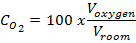
Where:
Voxygen is the volume of oxygen in the room in m3, calculated as in (ii), (iii), or (iv) below
Vroom is the total volume of the room, in m3
Normal evaporative losses
Over sufficiently long periods, the percentage of oxygen remaining in a room due to normal evaporation losses from a vessel is approximately:
Eq. 1.1

Where:
0.209 represents the normal concentration of oxygen in air (20.9%)
Given the evaporation loss rate for a vessel, the increase in nitrogen concentration can be calculated:
Eq. 1.2
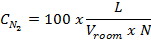
Where:
L is the evaporation rate of the dewar in m3 per hour
Vroom is the volume of the room
N is the number of air exchanges per hour from the room’s ventilation
Manufacturers usually quote the evaporation rate for their vessels as a volume of liquid nitrogen lost per day in the specifications of the dewar model (usually this information can be found on the manufacturer’s website), which must be converted to a volume of gaseous nitrogen produced per hour. Additionally, allowance should be made, by doubling these figures, for the deterioration of insulation performance over the lifetime of the vessel. Thus the evaporation loss rate that will be used is calculated:
Eq. 1.3

Where:
2 allows for an increased loss rate due to the deterioration of insulation
696 represents the gas factor for nitrogen (1 liter of liquid nitrogen expands to 696 liters of gas)
1000 accounts for the conversion from L to m3
And 24 converts from a loss rate per day to a loss rate per hour.
EXAMPLE
For example, a small microscope room measures 10ft x 12.5ft by 8ft tall, and contains one 15-liter storage dewar, whose evaporative loss is quoted by the manufacturer as 0.8L liquid nitrogen per day. This room has no fume hoods or other sources of increased ventilation, and thus has only 0.4 air exchanges per hour. Using equation 1.3, the evaporation loss rate is:
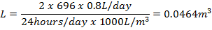
Given that 1 cubic foot is equal to 0.0283 cubic meters, the volume of the room can be calculated:
And the increase in nitrogen concentration, using equation 1.2, is:
Therefore, the resulting oxygen concentration, using equation 1.1, is:
In this case, the normal evaporation losses have an insignificant effect on the oxygen content of the room. However, where the increase in Nitrogen concentration, 


Filling losses
When a vessel is filled, some loss always occurs as it is cooled to liquid-nitrogen temperature. The British Compressed Gases Association, BCGA, recommends that a loss of 10% of the vessel’s capacity should be assumed in order to assess the risk from filling losses. We can calculate the volume of oxygen remaining in the room after filling:
Eq. 2.1
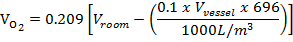
Where:

0.209 represents the normal concentration of oxygen in air (20.9%)
0.1 represents the loss of 10% of the vessel’s capacity
Vvessel is the vessel’s capacity in liters
696 represents the gas factor for nitrogen (1 liter of liquid nitrogen expands to 696 liters of gas)
The factor of 1000 is used to convert from the vessel volume from L to m3
EXAMPLE
A small room is used to house the filling station for other laboratories in the area. This room measures 10ft by 14ft by 10ft tall. A researcher wishes to fill a 34L storage dewar from the fill station.
Converting the room measurements to a volume in m3, we obtain:
Using equation 2.1, followed by equation 0, we calculate:
In this case, the oxygen level is very close to dipping below 19.5%. The researcher should consult their supervisor to determine if a full Oxygen Deficiency Hazard analysis should be conducted with the help of EHS.

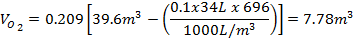
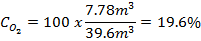
Spillage
For the spillage of the entire contents of a vessel:
Eq. 3.1

Again, 696 is the expansion factor for nitrogen from liquid to gas and dividing by 1000 accounts for the conversion from L to m3.
We then use equation 0 to calculate the oxygen concentration in the room.
EXAMPLE
If a researcher working in the small microscope room described above (which measures 10ft x 12.5ft x 8ft tall) were to spill the 15-liter dewar, we calculate the remaining oxygen concentration using equation 3.1 followed by equation 0:
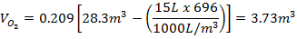
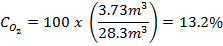
This spillage would significantly deplete the oxygen concentration, leading to an extremely dangerous situation for the researcher. The researcher should contact their supervisor and obtain help from EHS to conduct an Oxygen Deficiency Hazard analysis on this microscope room before performing any work with cryogens there.
Filling of a vessel followed by the spillage of its entire contents
Eq. 4.1
Where:
1.1 represents 10% filling loss + 100% loss of the vessel’s contents by spillage
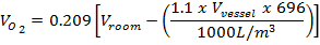
This is the worst case that should be considered in the risk assessment—both (ii) and (iii) are taken into account.
EXAMPLE
Let us consider a 10-liter dewar being filled at the aforementioned filling station, followed immediately by the spillage of its entire contents. Using equation 4.1 followed by equation 0, we calculate:
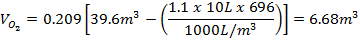
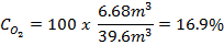
This calculation shows that even filling a 10L dewar in such a small space can be dangerous if the dewar were to spill during the filling operation.
If the risk assessment shows that oxygen depletion will occur (oxygen level below 19.5%) in any of these situations, EHS must perform an Oxygen Deficiency Hazard risk analysis. If the risk analysis shows an Oxygen Deficiency Hazard rating of 1 or greater, alternative arrangements must be considered or oxygen monitoring must be installed. Alternative arrangements may include:
- Positioning the vessels elsewhere.
- Using smaller vessels.
- Arranging for any pressure-relief devices to vent to a safe place outside of the room.
- Installing mechanical ventilation possibly linked to the low-oxygen alarm.
- Requiring staff to wear personal oxygen monitors.
_____________________

